2021年6月19日土曜日

Ubuntu 20.04/Debian 10(Buster)にDBクライアントDbGateをインストールする

DbGateはMySQLやPostgreSQLなどの様々なデータベースに対応したDBクライアントです。

・DbGateの画面(Ubuntu 20.04)

・DbGateの画面(Debian 10)

インストール方法

Ubuntu 20.04/Debian 10(Buster)にDBクライアントDbGateをインストールするには、以下のコマンドを実行します。
wget https://github.com/dbgate/dbgate/releases/latest/download/dbgate-latest.deb
sudo apt-get -y install ./dbgate-latest.deb

関連情報

・DbGateのwebサイト
https://dbgate.org/

2021年6月18日金曜日

Windows10にOpenSCADをインストールする

OpenSCADはコードで3Dモデルをデザイン出来ます。Windows10にOpenSCADをインストールするには、以下の手順を実行します。

インストール手順

1. OpenSCADのwebサイトのダウンロードページからx86 (64-bit) exe installerをクリックしてダウンロードします。
https://openscad.org/downloads.html

2. ダウンロードしたOpenSCAD-2021.01-x86-64-Installer.exeをダブルクリックして起動して、インストーラのInstallボタンをクリックします。

3. インストールが完了したらCloseボタンをクリックします。

4. WindowsメニューからOpenSCADをクリックして実行します。

関連情報

・そのほかの3Dプリンターを活用した記事は以下を参照してください。
OpenSCADまとめ

AlmaLinux8.3にVFXアプリNatronをインストールする

Natronは動画に視覚効果(VFX)をつける事のできるアプリケーションです。

〇Natronの画面(AlmaLinux 8)

インストール方法

AlmaLinuxにインストールするには、以下のコマンドを実行します。
sudo dnf -y install flatpak

sudo flatpak remote-add --if-not-exists flathub https://flathub.org/repo/flathub.flatpakrepo

sudo flatpak -y install flathub fr.natron.Natron

関連情報

・Natronの視覚効果・操作方法については、以下のページを参照してください。
動画に視覚効果をつける事のできるNatronのまとめ

・プロジェクトwebサイト
https://natrongithub.github.io/

・様々な動画に関するアプリケーションについては、以下のまとめを参照してください。
動画関連アプリケーションのまとめ

2021年6月17日木曜日

Raspberry Pi Zero/Raspberry Pi PicoとLazurite MJ2001を接続して、920MHz無線で通信する

送信側のRaspberry Pi PicoとMJ2001、受信側のRaspberry Pi ZeroとMJ2001の間で通信するには、以下の手順を実行します。
今回は単にRaspberry Pi Picoでの値をカウントするメッセージをRaspberry Pi Zeroで受信します。

〇Raspberry Pi PicoとLazurite MJ2001を接続した写真

開発手順

1. 必要部品の準備
・MJ2001(Lazurite Miniシリーズ、920J後継品)
https://www.switch-science.com/catalog/7162/
※Raspberry Pi Pico/Raspberry Pi Zeroそれぞれに接続するので2台必要です。

・Lazurite Mini writer Type B(Lazurite Miniシリーズ)
https://www.switch-science.com/catalog/2956/
※MJ2001にプログラムを書き込むのに必要です。これは1台でOKです。

・ピッチ変換基板 2×5⇔1×10
https://akizukidenshi.com/catalog/g/gP-14224/
※ハーフピッチ(1.27mm)を2.54mmピッチに変換してくれる基板です。変換基板を2枚用意します。

・ピンソケット 1.27mm 2×5(10P)
https://akizukidenshi.com/catalog/g/gC-13806/
※こちらも2個用意します。

・分割ロングピンソケット 1×42 (42P)
https://akizukidenshi.com/catalog/g/gC-05779/
※10ピン分に切っておきます。

2. 2台分の変換基板の作成&Lazurite MJ2001にtest920jプログラムを書き込み
LazuriteとRaspberry Pi Pico/Raspberry Pi Zeroを接続するための変換基板を2枚作成します。変換基板の作成方法は以下を参照してください。

Raspberry Pi ZeroとLazurite MJ2001を接続して、Lazurite上の青LEDをLチカする

3. Raspberry Pi Zero側: MJ2001の接続&Serialのraspi-configでSerial Portの有効化&pipenvのインストール&pyserialのインストールされた仮想環境の作成
以下の記事を参照して、Raspberry Pi Zero側の環境を整えます。
Raspberry Pi ZeroとLazurite MJ2001を接続して、Lazurite上の青LEDをLチカする

4. Raspberry Pi Zero側: 受信プログラムの作成と実行
以下のプログラムをmj2001_recv.pyとして保存して実行します。受信側のMJ2001のアドレスを表示するので控えておきます(sggma:で始まる表示の後の16進数が受信機のアドレスです)。
import serial
import time

PANID="0x1111"

try:
    ser = serial.Serial(port='/dev/serial0',baudrate=115200,timeout=None)

    # initialize subGHz
    ser.write("sgi\n".encode("utf-8"))
    ser.flush()
    line = ser.readline()
    print("result:{}".format(line.decode('utf-8').strip()))

    # start with ch=36 and PANID=0x1111
    ser.write(("sgb,36,"+PANID+",100,20\n").encode("utf-8"))
    ser.flush()
    line = ser.readline()
    print("result:{}".format(line.decode('utf-8').strip()))

    # get my address
    ser.write("sggma\n".encode("utf-8"))
    ser.flush()
    myaddress = ser.readline().decode('utf-8').strip().split(',')[1]
    print("sggma:{}".format(myaddress))

    # get send mode
    ser.write("sggsm\n".encode("utf-8"))
    ser.flush()
    line = ser.readline()
    print("result:{}".format(line.decode('utf-8').strip()))

    # Enable Rx
    #ser.write("sgre\n".encode("utf-8"))
    ser.write("sgra\r\n".encode("utf-8"))
    ser.flush()
    line = ser.readline()
    print("result:{}".format(line.decode('utf-8').strip()))

    try:
        while True:
            rl = ser.readline()
            #print(rl)
            recv = rl.decode('utf-8').strip().split(',')
            if len(recv) >= 8 and len(recv[8]) > 0:
                print("result:{}".format(recv[8]))
    except KeyboardInterrupt:
        # close
        ser.write("sgc\n".encode("utf-8"))
        ser.flush()
        line = ser.readline()
        print("result:{}".format(line.decode('utf-8').strip()))
finally:
    ser.close()

・実行コマンド
以下のコマンドで受信プログラムを実行します。
python3 mj2001_recv.py

5. Raspberry Pi Pico側: Raspberry Pi PicoとLazurite MJ2001の接続
Raspberry Pi Picoと変換基板を以下の様に接続します。

Raspberry Pi Pico 3V3ピン(Picoを裏側・USBを上にした時、左列の上から5番目) -> 変換ピンの10番ピン
Raspberry Pi Pico GNDピン(Picoを裏側・USBを上にした時、左列の上から3番目) -> 変換ピンの8番ピン
Raspberry Pi Pico GP0/UART0 Txピン(Picoを裏側・USBを上にした時、右列の上から1番目) -> 変換ピンの1番ピン
Raspberry Pi Pico GP1/UART0 Rxピン(Picoを裏側・USBを上にした時、右列の上から2番目) -> 変換ピンの2番ピン

変換コネクタとMJ2001は2x5ピンを合わせて接続します。ピンの位置などがずれないように合わせます。

6.Raspberry Pi Pico側: MicroPythonのプログラム書き込みと実行
Thonnyで以下のMicroPythonプログラムを書き込んで実行します。dest_addrは手順4で控えた受信機のアドレスを設定します。受信側のRaspberry Pi Zeroに「count:N」のメッセージが表示されることを確認します。
import machine 
import time

PANID="0x11111"
dest_addr="0xABCD"

# initialize UART.
uart = machine.UART(0, 115200)

ct = 0
# initialize subGHz
uart.write('sgi\n')
print(uart.readline())


while True:
    # begin with ch=36,PANID=0x1111
    uart.write("sgb,36,"+PANID+",100,20\n")
    print(uart.readline())

    # send count message
    uart.write("w,count:{}    \n".format(ct))
    print(uart.readline())
    uart.write("sgs,"+PANID+","+dest_addr+"\n")
    print(uart.readline())
    
    # close
    uart.write("sgc\n")
    print(uart.readline())

    ct=ct+1
    time.sleep(1)

関連情報

Raspberry Pi ZeroとLazurite MJ2001を接続して、Lazurite上の青LEDをLチカする

Windows10にPython3.9とThonnyをインストールする

Raspberry Pi ZeroとLazurite MJ2001を接続して、Lazurite上の青LEDをLチカする

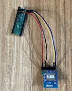
Lazurite MJ2001は低消費電力で920MHz無線に対応したマイコンモジュールです。Raspberry Pi ZeroとLazurite MJ2001を接続して、Lazurite上の青LEDをLチカするには、以下の手順を実行します。

〇Raspberry Pi ZeroとLazurite MJ2001を接続した写真

開発手順

1. 必要部品の準備
・MJ2001(Lazurite Miniシリーズ、920J後継品)
https://www.switch-science.com/catalog/7162/

・Lazurite Mini writer Type B(Lazurite Miniシリーズ)
https://www.switch-science.com/catalog/2956/
※MJ2001にプログラムを書き込むのに必要です。

・ピッチ変換基板 2×5⇔1×10
https://akizukidenshi.com/catalog/g/gP-14224/
※ハーフピッチ(1.27mm)を2.54mmピッチに変換してくれる基板です。

・ピンソケット 1.27mm 2×5(10P)
https://akizukidenshi.com/catalog/g/gC-13806/

・分割ロングピンソケット 1×42 (42P)
https://akizukidenshi.com/catalog/g/gC-05779/
※10ピン分に切っておきます。

あと、Raspberry Pi Zeroも用意します。

2. 変換基板の作成
ピッチ変換基板・ピンソケット1.27mm 2×5(10P)と10ピンにカットした分割ロングピンソケットをハンダ付けします。コネクタはいずれとも文字が印刷されている面に取り付けます。

〇ピッチ変換基板・ピンソケット1.27mm 2×5(10P)と10ピンにカットした分割ロングピンソケット

〇ピッチ変換基板・ピンソケット1.27mm 2×5(10P)と10ピンにカットした分割ロングピンソケットをハンダ付けした写真(とMJ2001)

3. Lazurite MJ2001にtest920jプログラムを書き込み
Lazurite IDEを以下からダウンロードしてWindowsマシンにインストールします。example/10.920j/test920jのプログラムを開いて、MJ2001に書き込みます。
https://www.lapis-tech.com/lazurite-jp/download

WindowsマシンとLazurite MJ2001の接続は以下のページにある「インターフェイス仕様」のPDFを参照します。
Lazurite mini writer (Type B)ラズライト
https://www.lapis-tech.com/lazurite-jp/products/lazurite-mini-writer-type-b

4. Raspberry Pi Zero側:raspi-configでSerial Portの有効化
Serialポートを有効化するために以下を実行します。
1) 以下のコマンドを実行します。
sudo raspi-config

2) Interface Optionsを選択します

3) P6 Serial Portを選択します

4) Would you like a login shell to be accessible over serial?にNoと答えます

5) Would you like the serial port hardware to be enabled?にYesと答えます

6) Okを選択します

7) Finishを選択します

8 ) Would you like to reboot now?でYesを選択して、リブートします

5. Raspberry Pi ZeroとMJ2001の接続
・以下の様にRaspberry Pi Zeroと変換コネクタを接続します。
Raspberry Pi Zero 3.3Vピン(SDカードスロットを上方向にした時、左列のピンの一番上) -> 変換ピンの10番ピン
Raspberry Pi Zero GNDピン(SDカードスロットを上方向にした時、右列のピンの上から3番目) -> 変換ピンの8番ピン
Raspberry Pi Zero GPIO15/Txピン(SDカードスロットを上方向にした時、右列のピンの上から4番目) -> 変換ピンの1番ピン
Raspberry Pi Zero GPIO16/Rxピン(SDカードスロットを上方向にした時、右列のピンの上から5番目) -> 変換ピンの2番ピン

変換コネクタとMJ2001は2x5ピンを合わせて接続します。ピンの位置などがずれないように合わせます。

6. Raspberry Pi Zero側:pipenvのインストール
sudo apt-get -y install python3-pip python3-distutils python3-dev python3-testresources

sudo pip3 install --upgrade setuptools

sudo pip3 install pipenv

echo "export PIPENV_VENV_IN_PROJECT=true" >> ~/.bashrc

source ~/.bashrc

7. Raspberry Pi Zero側:pyserialのインストール
以下のコマンドで、pyserialをインストールした仮想環境を作成します。
mkdir -p ./pyserial

cd ./pyserial

pipenv --python 3

pipenv install pyserial

pipenv shell

8. Raspberry Pi Zero側:Raspberry Piでプログラムの実行
以下のプログラムをmj2001blink.pyとして、保存し実行します。
※プログラムでシリアル通信で送信しているコマンドは以下のページを参照してください。
Lazurite920J 初期プログラム、インタフェース仕様
https://www.lapis-tech.com/lazurite-jp/contents/Serial920J/Serial920J.html

import serial
import time

try:
    ser = serial.Serial(port='/dev/serial0',baudrate=115200,timeout=None)
    ser.write("pm,26,o\n".encode("utf-8"))
    ser.flush()
    line = ser.readline()
    print("result:{}".format(line.decode('utf-8').strip()))
    time.sleep(2)
    print("setup")
    while True:
        ser.write("dw,26,0\n".encode("utf-8"))
        ser.flush()
        line = ser.readline()
        print("result:{}".format(line.decode('utf-8').strip()))
        print("on")
        time.sleep(2)

        ser.write("dw,26,1\n".encode("utf-8"))
        ser.flush()
        line = ser.readline()
        print("result:{}".format(line.decode('utf-8').strip()))
        print("off")
        time.sleep(2)
finally:
    ser.close()

・実行コマンド
以下のコマンドを実行して、MJ2001の青色LEDが2秒おきに点滅する事を確認します。
python3 mj2001blink.py

関連項目

Raspberry Pi Zero/Raspberry Pi PicoとLazurite MJ2001を接続して、920MHz無線で通信する

Raspberry Pi Zeroと小型ターンテーブルをREST APIで制御する

Raspberry Pi Picoと照度センサーモジュールで照度を測る

Raspberry Pi Picoと照度センサーモジュールで照度を測るには、以下の手順を実行します。
照度モジュールは、秋月電子さんの以下の照度センサーモジュールを使用しました。i2cでRaspberry Pi Picoと通信します。

TSL25721使用 照度センサーモジュール
https://akizukidenshi.com/catalog/g/gK-15536/

実行手順

1. ピンのハンダ付けと、Raspberry Pi Zeroへの接続
・Raspberry Pi Picoとジャンパー線で接続した照度センサーモジュール

Raspberry Pi Picoと照度センサーモジュールは以下の様に接続します(モジュールの裏面にピン略称が印刷されています)
Raspberry Pi Pico 3.3Vピン(ピン36) -> TSL25721のVIN
Raspberry Pi Pico GP0ピン(ピン1) -> TSL25721のSDA
Raspberry Pi Pico GP1ピン(ピン2) -> TSL25721のSCL
Raspberry Pi Pico GNDピン(ピン38) -> TSL25721のGND

2. プログラムの作成と実行
以下のプログラムをmain.pyファイルとしてRaspberry Pi Picoに保存して、実行します。
import time
from machine import Pin, I2C
i2c=I2C(0, scl=Pin(1), sda=Pin(0), freq=400000)

addr_tsl25721=0x39
#print(i2c.scan())
FIELD_COMMAND = 0x80 # Write
FIELD_TYPE = 0x20 #  Auto-increment protocol transaction

REG_CONTROL = 0x0F # Control Register
VAL_CONTROL_RESET = 0x00 # Reset Value for Control Register
REG_CONFIG = 0x0D # Config Register
VAL_CONFIG_RESET = 0x00 # Reset Value for Config Register
REG_ATIME = 0x01 # ATIME(ALS time) Register
VAL_ATIME_C64 = 0xC0 # INTEG_CYCLE=64, Time=175ms
REG_ENABLE = 0x00 # Enable Register
VAL_ENABLE_PON = 0x01 # Power ON
VAL_ENABLE_AEN = 0x02 # ALS Enable
VAL_ENABLE = VAL_ENABLE_PON | VAL_ENABLE_AEN

REG_C0DATA = 0x14 # CH0 ADC low data register

# Initialize
# Reset Control Register
buf = bytearray(1)

buf[0] = VAL_CONTROL_RESET
i2c.writeto_mem(addr_tsl25721, FIELD_COMMAND | FIELD_TYPE | REG_CONTROL, buf)

# Reset Config Register
buf[0] = VAL_CONFIG_RESET
i2c.writeto_mem(addr_tsl25721, FIELD_COMMAND | FIELD_TYPE | REG_CONFIG, buf)

# Set ALS time
buf[0] = VAL_ATIME_C64
i2c.writeto_mem(addr_tsl25721, FIELD_COMMAND | FIELD_TYPE | REG_ATIME, buf)

# Power on and enable ALS
buf[0] = VAL_ENABLE
i2c.writeto_mem(addr_tsl25721, FIELD_COMMAND | FIELD_TYPE | REG_ENABLE, buf)
time.sleep(1)

def read_lux():
  atime = 0xC0 # 192
  gain = 1.0

  dat = i2c.readfrom_mem(addr_tsl25721, FIELD_COMMAND | FIELD_TYPE | REG_C0DATA, 4)
  adc0 = (dat[1] << 8) | dat[0]
  adc1 = (dat[3] << 8) | dat[2] 

  cpl = (2.73 * (256 - atime) * gain)/(60.0)
  lux1 = ((adc0 * 1.00) - (adc1 * 1.87)) / cpl
  lux2 = ((adc0 * 0.63) - (adc1 * 1.00)) / cpl
  lux = 0
  if ((lux1 <= 0) and (lux2 <= 0)) :
    lux = 0
  if (lux1 > lux2) :
    lux = lux1
  elif (lux1 < lux2) :
    lux = lux2

  return lux

while True:
  lux= read_lux()
  print("lux:{:.1f}".format(lux))
  time.sleep(1)

AlmaLinux8.3に動画編集アプリShotcutをインストールする

Shotcutは動画編集アプリケーションです。

〇Shotcutの画面

インストール方法

以下のコマンドを実行します。
sudo dnf -y install flatpak

sudo flatpak remote-add --if-not-exists flathub https://flathub.org/repo/flathub.flatpakrepo

sudo flatpak -y install flathub org.shotcut.Shotcut

関連情報

・Shotcutに関するまとめは以下のページを参照してください。
動画編集アプリShotcutのまとめ

・プロジェクトwebサイト
https://shotcut.org/

・様々な動画に関するアプリケーションについては、以下のまとめを参照してください。
動画関連アプリケーションのまとめ